College of Engineering
14 Studying the Manual Control of a Continuum Soft Manipulator
Jacob Hirst (University of Utah)
Faculty Mentor: Haohan Zhang (Mechanical Engineering, University of Utah)
Background
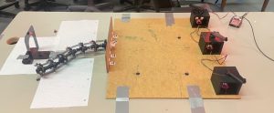
Due to their highly flexible structures, continuum manipulators (CM) are uniquely suited for many tasks (e.g., surgery, inspection) beyond the capabilities of traditional manipulators. In my UROP research in Spring 2022, we developed a CM whose shape can be controlled by pulling 3 cables routed through its segments. These cables were controlled by electrical motors with pulleys. Figure 1 shows a picture of the original CM used during the UROP research. Due to the under- actuated nature of this manipulator, controlling its shape automatically with motors turns out to be a complex mathematical problem. Because of the complexity, we decided to use a data-driven machine learning approach to help solve this. The machine learning library that we used is an open-source python library called BINGO, made by Dr. Jacob Hochhalter and his colleagues at NASA.
Problem
The model made to represent the shape of the CM at different motor positions was accurate to our expectations, but the robot is unpredictable in how it goes from one position (or shape) to another. This results in the question – How can we control how the CM moves from point A to point B? To study this, we need to first figure out how we want the CM to be controlled.
Methods
The first task was to create a whole new CM. We did this for a couple of reasons. First, the original CM had lots of friction and one broken universal joint, which caused the motion of the CM to be less predictable and fluid. Second, we planned to use VICON to help track the motion of the CM, and there were no permanent mounts for the VICON markers. Figure 2 shows an image of the new vertebrae prototype, which was modeled using Solidworks CAD. The new vertebrae features 3 voids that allow you to insert infrared-reflecting markers that VICON is able to track.
The next task was to create mechanical cranks for humans to be able to control the lengths of the cables that channel through the CM. These cranks were connected to pulleys that retracted and extended the cables when rotated. The cranks were also connected to Qwiic Twist encoders from SparkFun. The encoders tracked the motion of the crank and therefore would allow us to track the lengths of the cables and later study how the CM moved from those lengths. The encoders were programmed to output their data to a CSV when prompted by a PySimpleGUI using Arduino IDE.
Once the new CM and mechanical cranks were developed, we were then able to collect data. VICON was used to track the motion of the CM as 3 volunteers moved the CM from a starting marker to a goal marker using the mechanical cranks discussed earlier. The VICON data and encoder data were synchronized by simultaneously recording a voltage reading from the Arduino pins. Since the frequency of the VICON data being collected was higher than the frequency of the encoders, a high voltage was written to an Arduino analog pin every time that an encoder value was read. This voltage went through a BNC cable, and was written into the VICON data. The VICON and encoder data were synchronized in post-processing using these voltage readings. Pictures of the full data collection setup are shown in Figures 3 and Figure 4. Our goal was to create 3 BINGO models that predict the x, y and z coordinates of the far end of the CM using the encoder values from the mechanical cranks as an input, with a MAE of 5 mm for each degree of freedom.
Results
With the synchronized data, we used BINGO to create a model that predicts the X, Y and Z coordinates of the end of the CM with 3 given encoder values. The models had a MAE of 5.25 mm, 11.26 mm, and 1.73 mm for the x, y and z coordinates, respectively. We reached our goal with the z axis, but the x and y axis need more data and more time to learn in order to become more accurate.
Conclusion
The bulk of this research project has been completed, and we are proud of the results we have. The BINGO models obviously do not show the MAE we desired, but that is mostly due to a mistake made during the data collections, which limited the size of our datasets. In future work, there needs to be more iterations of the CM, as well as more data collection. This way, we will hopefully be able to create a more accurate BINGO model that can more accurately determine each degree of freedom of the CM.
Figures
Figure 1: UROP CM controlled by motors from the research done in Spring 2022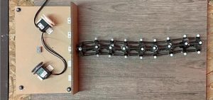
Figure 2: New vertebrae prototype featuring mounts for the VICON markers
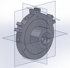
Figure 3: Data collection setup with mechanical cranks (front view)
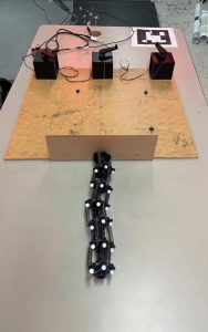
Figure 4: Data collection setup with mechanical cranks (side view)