Visualizing Single Channel Currents With the Patch-Clamp Method
Caleb Bevan
Objective 3: Explain how the patch-clamp method is used to study the properties of individual ion channel proteins.
Since the discovery of electrical activity in neurons in the late 18th century, electrophysiologists refined their methods of measuring electrical activity in neurons. It was not until 1928 that Edgar Adrian and Detlev Bronk published papers in which a cell was punctured by a sharp metal electrode to record the cell’s electrical activity. Electrode technology progressed slowly, finally culminating in the invention of a glass micropipette filled with saline solution which penetrated the cell.
This was made possible by two properties of glass:
- glass is a terrific electrical insulator and cannot in any way conduct electricity
- when a tiny glass tube is heated and stretched, the hole in the middle of it gets smaller and smaller (down to as small as 0.1 μm)
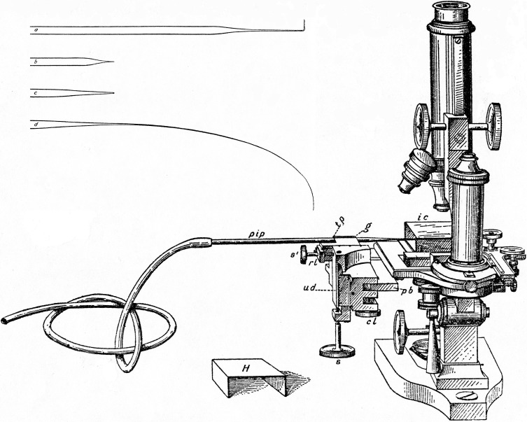 For almost a century, glass micropipettes were the standard used by electrophysiologists to record from cells. Marshall Barber invented the micropipette and micromanipulator. The micromanipulator is a modified microscope stage that moves the sharp pipette by tiny increments until it contacts, then penetrates, the cell.
 Around 1980, the German electrophysiologists Erwin Neher and Bert Sakmann discovered a new way of recording electrical activity in neurons (and other cells). It is called a patch clamp: “patch ” because the membrane attached to the pipette is a small circular region, while “clamp” is an old electrophysiology word for a device that holds a constant voltage (potential).
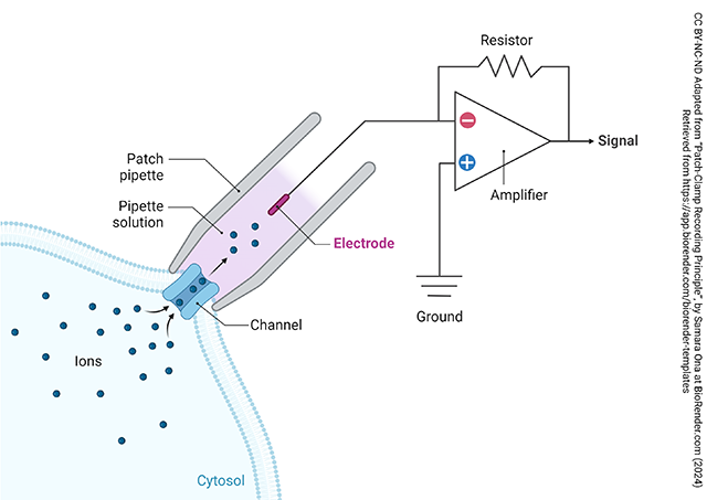
Instead of a sharp, microscopically pointed pipette, as had been used before, now a fire-polished pipette (still tiny, about 2-3 μm diameter) is used to attach to the cell. With luck, a single channel can be isolated inside the insulating glass and the investigator can measure electrical activity through a single ion channel as described in the previous chapter.
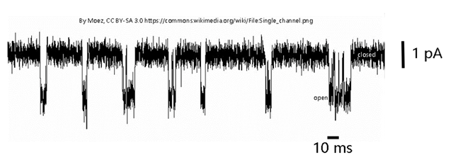 An example of one of these single channel recordings is shown above. The X axis is time; a bar representing 10 msec is shown. The Y axis represents current. (One weird thing about these records is that by convention, inward current is shown as a downward deflection.) In this example, we are seeing a set of inward currents of about 2 pA (2 x 10⁻⁹ Amperes) magnitude. This represents a flow of about 6000 electrons (or 6000 positive charges, in the case of Na+ or K+) per msec. When you think about how tiny an electron is (9 × 10-31 kilograms), you can appreciate how sensitive an instrument a single ion channel is (i.e., about 9 × 10-28 kilograms flow).
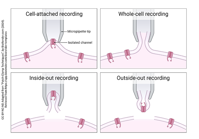
By adjusting the suction on the pipette and the tension supplied by the micromanipulator, the investigator can obtain several different configurations of the single channel. The solution inside and outside the pipette can be altered to provide whatever concentration of ions the investigator wants to study (e.g. change the direction of diffusion).
The cell-attached recording is shown at upper left. The pipette isolates a single channel, and the investigator can change the composition of the solution in the pipette tip (gray shading) but not the composition of the cytosol (pink).
The whole-cell recording is shown at upper right. By applying gentle suction which exceeds the ductile strength (resistance to stretching) of the membrane patch, the pipette ends up sampling the activity of all the ion channels in the cell membrane. Like the cell-attached recording, the pipette solution can be changed but the cytosol cannot.
In an inside-out recording configuration, the micromanipulator is gently pulled away from the cell, ripping away the membrane patch in its original orientation. The pipette solution now mimics the extracellular fluid and the bath solution mimics the cytosol.
In an outside-out recording configuration, a different pull of the micromanipulator is used which “flips” the patch and now the investigator can put artificial cytosol in the pipette tip and whatever bath solution is needed for the study.
Media Attributions
- Glass micropipette and micromanipulator © Marshall Barber and Allan H Bretag is licensed under a CC BY-NC-SA (Attribution NonCommercial ShareAlike) license
- Patch-Clamp Recording Principle © Samara Ono adapted by Jim Hutchins is licensed under a CC BY-NC-ND (Attribution NonCommercial NoDerivatives) license
- Current flow through ion channels © Moez is licensed under a CC BY-SA (Attribution ShareAlike) license
- Patch-Clamp Techniques © BioRender adapted by Jim Hutchins is licensed under a CC BY-NC-ND (Attribution NonCommercial NoDerivatives) license
