College of Science
96 The Sperm Racetrack: A Novel Microfluidic Method for Motility-Based Sperm Separation
Lauren Hulse and Nitin Phadnis
Faculty Mentor: Nitin Phadnis (School of Biological Sciences, University of Utah)
Introduction
Around 15% of couples globally face infertility issues [1], with male factors accounting for approximately 20-30% of these cases [2]. A 2015 study by Agarwal revealed that 30 million men worldwide experience symptoms of infertility [2]. This condition can be attributed to various causes in males specifically, such as environmental factors, infections, or azoospermia — a complete absence of sperm due to hormonal imbalances or anatomical issues like injuries to the male genitalia. An additional contributing factor to male infertility is genetic disorders that impact fertility by causing sperm dysfunction via distorting alleles. Distorting alleles are selfish alleles that alter cell behavior – in this case sperm behavior – by sabotaging their non-distorting homologous alleles at some point between spermatogenesis and fertilization [3]. This phenomenon has been seen across a wide range of species, from Drosophila to mouse [4-5]. One way that these selfish alleles could gain an advantage over other alleles is by making the selfish sperm swim faster, enhancing the transmission of their genetic material to future generations. Understanding this swimming-related distortion could lead to a greater understanding of male infertility and help aid in the generation of more effective treatments.
To accomplish this identification and characterization, we must be able to sort, and separate sperm based on their swimming speed. Unfortunately, existing techniques for handling swimming sperm do not allow fast-swimming sperm to be separated from slow-swimming sperm.
Currently available sperm-sorting techniques largely function to merely separate dead or immotile sperm from motile sperm. The typical motile sperm selection methods used for assisted reproductive technology (ART) include the swim-up technique and density gradient centrifugation. [6] These techniques cause cellular damage by increasing the level of cell-to-cell contact. This produces high levels of reactive oxygen species which has been shown to cause cellular damage and sperm dysfunction [7], inhibiting the effectiveness of ART and complicating the further study of the differences between fast and slow sperm [8]. Fortunately, advancements in microfluidics make possible the development of sperm sorting devices that cause minimal cellular damage by avoiding centrifugation. Microfluidics is an emerging field that involves the manipulation of fluid volumes on the microscale using channels with dimensions ranging from tens to hundreds of micrometers [9].
Several innovative microfluidic devices have been engineered to use biological behaviors of sperm, most notably rheotaxis. [10-16] Rheotaxis is a passive physical process in which sperm orient to swim against a counterflow force. [17] Like how wind pushes the largest surface of a weathervane to align it with the wind direction, the long, light tails of sperm are pushed by the counterflow force to orient them into the flow. Currently available rheotaxis-based devices sort motile sperm from non-motile sperm with minimal damage but do not separate sperm based on their relative swimming abilities.
Therefore, there is an obvious need for a microfluidic device that addresses the two above shortcomings. The device should preferably use a biology-inspired design that harnesses sperm’s natural response to counterflow (rheotaxis) to systematically sort a semen sample based on the speed of the sperm in a sample. The device must also allow for an effective extraction of the separated subgroups post-sorting for a more detailed investigation into the genetic differences between the sperm. With such a device, we will be able to identify and characterize the genomic loci that drive variation in swimming speed. The ‘Sperm Racetrack’ aims to achieve these design requirements through a simple design: a straight channel with evenly spaced extraction ‘ports’, and the application of counterflow to the straight channel. It ultimately aims to aid in promoting the identification of a new source of male infertility, which could lead to new fertility treatments.
Background
Several microfluidic devices have been designed and developed as alternatives to the swim-up procedure and density gradient centrifugation in recent years. The microfluidic devices currently available specifically harness sperm’s properties of chemotaxis, thermotaxis, and rheotaxis, to create gradients to which sperm respond. [10-16] . In the context of sperm swimming, chemotaxis involves the movement of sperm towards chemical attractants, such as progesterone, released by the egg. Sperm respond to these chemical attractants by swimming faster and straighter. [6] Thermotaxis is similar: sperm orient faster and swim straighter as they get nearer to warmth. There is about a 2°C difference between the oviduct and the fertilization site, naturally attracting the sperm towards the egg.[6] Both principles can be recreated in vitro via a progesterone or temperature gradient in a microfluidic channel, but these gradients can be difficult to maintain over time. Rheotaxis more sustainably mimics the microenvironment of the oviduct in vitro than chemotaxis or thermotaxis. In vivo, this counterflow is created by the flow of cervical mucus in the oviduct. [18] Rheotaxis can be induced in vitro through the introduction of counterflow at a similar rate to the rate of mucosal flow in the oviduct.
Several microfluidic devices that harness rheotaxis have been previously created, including Sarbandi’s 2021 biomimetic microfluidic device [15], and Sharma’s 2022 device [16]. Both unique designs did separate sperm based on motility but could not sort motile sperm into groups based on their relative motility. They also could not extract the separated groups without re-mixing the separated motile and immotile sperm. Our device overcomes both shortcomings by sorting sperm into groups based on their swimming speed rather than motility and actually extracting the groups of sperm without mixing fast and slow groups. The separated groups will then be subjected to behavioral, morphological and, in the future, genetic assays. These assays will allow us to identify the characteristics of sperm that make them good or bad swimmers, and to relate these changes to male infertility and other phenomena of general biological interest such as segregation distortion and sperm competition. Ultimately, we hope that this device will lead to better understanding of sperm biology and potentially better treatments for male fertility.
Design
The overall design of the device is a straight channel in which sperm will swim, plusadditional design elements for inserting and extracting sperm and fluids, and a vacuum layer for removing unwanted bubbles. The microfluidic device was initially designed in AutoCAD (Product Version V.58.M.214, AutoCAD 2025) (Figure 1). The design consists of a vacuum layer and a flow layer separated by a 100-micron silicone membrane. The flow layer will hold the counterflow media and the introduced sperm sample, sitting on top of the membrane. The flow layer features a 6.5 cm straight channel with a width of 2 mm. This mimics the anatomy of the vaginal canal, at a microfluidic level. The channel has 7 evenly spaced extraction ports along it, labeled E7-1 in Figure 1. They are spaced 0.50 cm apart. This allowed for a separation of sperm into 6 subgroups based on their relative speed, allowing for a range of swim speeds and motilities to be analyzed. These are blocked by solid plugs made of 1.0 mm-diameter optical fiber during the run, but used to extract the sample post-run. Each port has a specific function. From top to bottom (Figure 1), the ports are as follows: first is the counterflow port (C). This is where the counterflow is introduced to the device. The following 6 ports of the device are the extraction ports. These are used to remove the sample from the device post- sorting. Next is the injection port (E1), which is the location where semen samples are introduced. Finally, we have the waste port (W), making any removal of excess media/sample possible.
We created a vacuum layer to remove problematic bubbles from the flow layer that might prevent sperm swimming or alter counterflow rates. It sits below the membrane and the flow layer and will be attached to a 30 cc syringe to create a vacuum effect via a syringe lock. The vacuum layer also features several cross patterns forming ‘columns’ to prevent membrane deflection, which could create uneven counterflow rates.
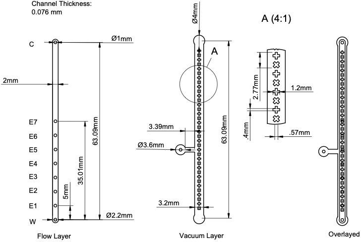
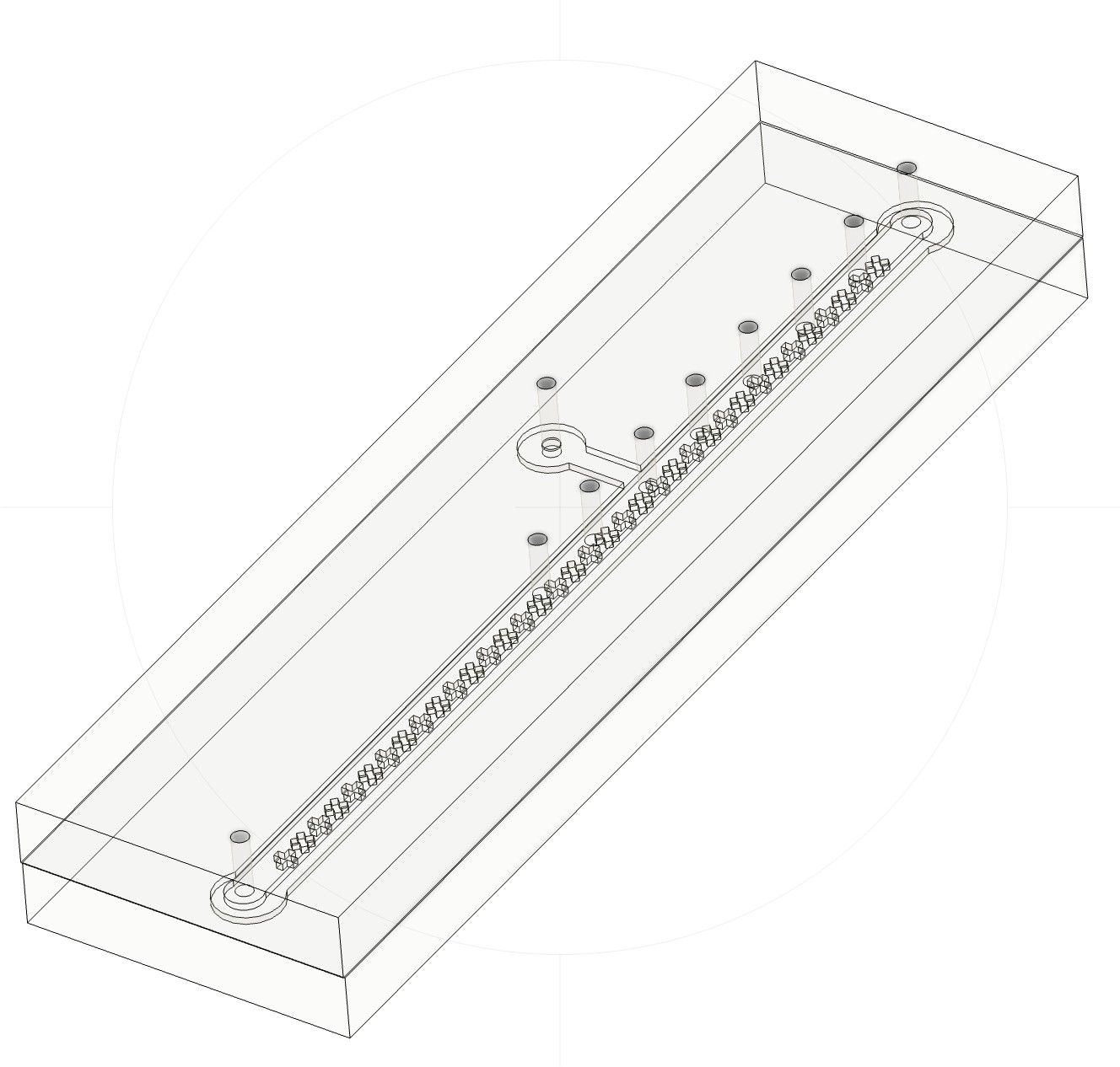
Figure 1. (Left) AutoCAD drawings of the Sperm Racetrack. (Right) Rendition of fabricated device from Fusion360.
Fabrication
The fabrication process of the device was based on rapid prototyping methods, using soft lithography (printing of soft materials). Broadly, molds were laser-cut for all layers of the device, which were then cast in polydimethylsiloxane (PDMS), and bonded using plasma etching techniques, as is standard in soft lithography. The use of a mold allowed for the creation of 3D structures on the microscale. Specifically, molds were laser-cut from the AutoCAD channel designs out of 3M Scotchcal Marking Film (3M, Product ID: SC 50-12 White), a material like electrical tape, and mounted them onto square Petri dishes. These were then cast the molds in PDMS and cured overnight in an oven set at 70°C (Figure 2a). After curing, the PDMS was removed from the mold to reveal the flow and vacuum layers. Next, extraction ports were then punched into the flow layer with a 1.0 mm hole punch. The channel was then masked with laser cut 3M Scotchcal Marking Film, cut to match the dimensions of the flow channel. 3 minutes of Corona Plasma Etching on both the PDMS-cast flow layer and one side of the 100-micron silicone membrane to bond them together.
After bonding the flow layer and the membrane, a 1.0 mm port was punched into the vacuum access channel, through both the PDMS and the silicone membrane, to allow for access to the vacuum layer. The vacuum layer with a laser cut piece of marking film matching its dimensions, and 3 minutes of corona etching on both the vacuum layer and the other side of the membrane to bond all layers together. The device was placed back into the 70°C oven overnight to seal the bonding. The final device is shown in Figure 2b.
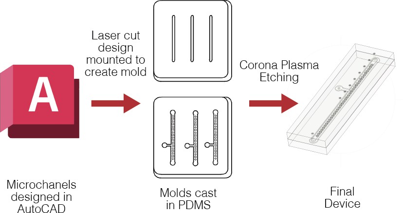

Figure 2. Fabrication and Experimental Setup. Top: Fabrication process. PDMS filled molds, with laser-cut CAD design inlaid. Bottom: Fully bonded device (quarter for scale)
Clinical
Sample Acquisition
All 3 semen samples used in this experiment were obtained from adult males visiting the Utah Center for Reproductive Medicine. All were consented under an IRB-approved protocol at the University of Utah by Kenneth Aston in the Department of Andrology.
Race Protocol
The device specifically mimics the gentle counterflow seen in the oviduct in vitro. Several preliminary experiments were completed, which will not be mentioned here, to determine that a counterflow of 0.092 ul/min elicited the rheotaxis response of sperm. On average, sperm swim at around 50 m/sec [19], thus it should only take ~22 minutes for the sperm to swim the full length of the channel (~6.5 cm). To account for slower sperm, and for individuals who do not have highly motile sperm, the sperm were allowed to swim for 30 minutes against the counterflow before extraction.
We first prepared the device by blocking the extraction ports and the injection port with small segments of 1.0 mm optical fiber. The counterflow port was then connected to a syringe pump holding a 100 uL Gastight Glass Syringe (Model 1710 TLL, PTFE Luer Lock), via 1.0 mm polytetrafluoroethylene (PTFE) tubing (Masterflex transfer tubing, microbore PTFE, 0.22” ID x 0.042” OD). Next, the waste port was routed to a collection container with the same PTFE tubing. The vacuum layer is connected to the 30cc syringe (Global Medical Products, Model 1202543 30 CC Luer lock Syringe) via this tubing, and the ‘vacuum’ is created via the syringe lock.
To create an environment with all the appropriate components for sperm to survive, the device was filled with Human Tubal Fluid (HTF) + 1% Bovine Serum Albumin (BSA) (Sigma Aldrich Corporation, MR-070-D). The addition of 1% BSA aids in lubricating the channel to prevent sperm sticking to the channel. Once the device was filled, and no air bubbles were present in the channel, the syringe pump was set to 0.092 ul/min. This counterflow speed was maintained throughout the race. Subsequently, 2.5 microliters of semen sample was introduced to the device via a 1-10 um micropipette, into the injection port. Following this, the injection port was re-blocked with optical fiber. The sperm were then allowed to swim for 30 minutes in the microfluidic channel. The experimental setup was observed via a Nikon Eclipse TE300 Inverted Microscope, with a 20x magnification objective. See Figure 2c for the experimental setup illustrated. (Figure 3)
Following the 30 minutes of sperm swimming, the process of recording the results of the race and collecting the separated sperm was begun. Each segment of the device was recorded using an AmScope 4k Series 2160P Camera (also, pure sample videos were taken before loading the device). Each segment was then extracted by loading HTF + 1% BSA into the first port of the segment, pushing the sample out of the subsequent port into a cryotube. (Figure 3) The extraction is done in sequential order from the waste segment – segment 6 of the device. 2 ul of each aliquot was placed on individual glass slides and recorded video with the AmScope camera. A Makler sperm counting chamber was used to count the number of sperm in each aliquot. Following this visualization and counting, the aliquots and pure samples were stored at -80°C to allow for future genetic assays to be performed.
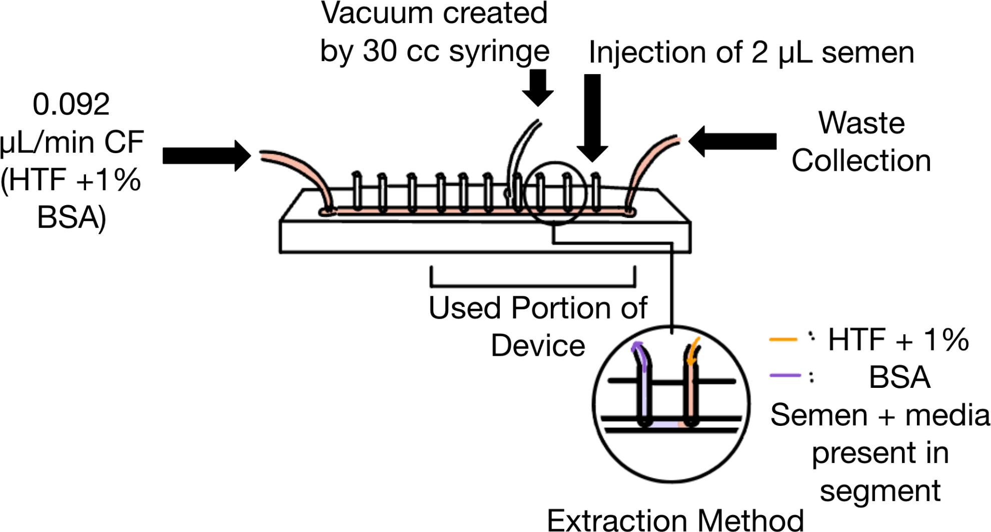
Figure 3. Experimental setup and extraction method. Counterflow is introduced from the left side, and sperm is introduced to the device via the 1st port to the left of the waste port. Vacuum is created via the port designed into the vacuum layer. Each extraction port is blocked with a small portion of 1.0 mm optical fiber. The sorted sperm are extracted through the infusion of HTF + 1% BSA via a syringe pump into the right port of a targeted segment. The extracted solution of sperm + media is collected through the left port of the targeted segment.
Swimming Characterization with CASA
In keeping with best practices, all videos were analyzed using the CASA plugin in ImageJ v1.51k [20]. CASA measures several aspects of sperm swimming through motion tracking algorithms. It produces several key behavioral parameters, such as the sperm’s curvilinear velocity (VCL), straight-line velocity (VSL), and average path velocity (VAP). All velocities are reported in um/sec.The VCL describes the point to point velocity of the sperm per second. The VSL is calculated using the straight line distance between the first point and the last point of a sperm track, and represents the straight-line distance that the sperm traveled. The VAP represents a smoothed version of the VCL to ignore the side to side movements of the sperm head. It also provides details about the sperm’s linearity, wobble level (sperms head movement side-to-side calculated by VAP/VCL), and the percent motility of sperm in the video. [20] Sperm linearity describes the amount of curvature in a sperm’s swimming path, and is determined by dividing VSL/VAP.
Preliminary processing using the base model of CASA revealed that the originally included algorithms could not efficiently differentiate between immotile sperm and debris in the channel. To combat this issue, three new motion tracking algorithms were added to the CASA plugin, to aid in optimizing sperm tracking. These included a minimum net distance traveled by the sperm in pixels (over the whole video), a minimum net distance traveled (in pixels)/frame of video, and an option to print an associated ID for each individual sperm tracked. These new additions ultimately served to focus the tracking to only be on sperm, not on any non-moving debris present in the channel. This optimized plugin was ultimately run on videos thresholded to only include sperm heads. The parameters listed in Figure 4 were used in all analyses.
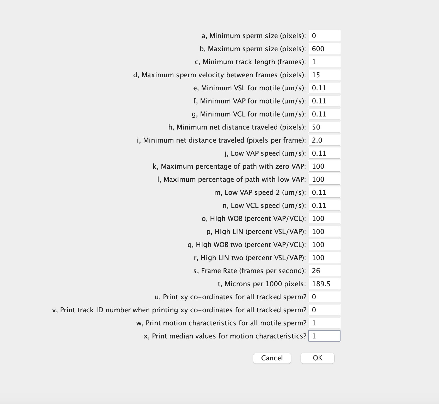
Figure 4. CASA parameters used in all analyses.
Sperm Distribution Along Channel
Investigation of the distribution of sperm along the channel was also undergone. This involved loading 2 uL of the extracted aliquots onto a Makler Sperm Counting Chamber. The number of motile and non-motile sperm in each row of 10 squares were counted. These numbers correspond to millions of sperm/ mL of sample. This information can provide insight between the competition between sperm based on their swimming speed.
Sample Size
3 separate samples were run on separate devices to test the variability of samples. Additionally, 1 of these samples was run on 3 separate devices to test the variability between devices. The goal is to run more tests on this device in the future to generate more data and better describe the effectiveness of our design.
Statistical Method
All data is expressed as a mean standard deviation. Statistical analyses were performed via linear models of the behaviors of sperm in different segments of the device. The specific behavior characteristics tested included VSL, VAP, VCL, linearity, and wobble level. Differences were considered significant when p < 0.05. All linear models were of the form statistic ~ segment, where statistic is VSL, VAP, or similar, and segment is the number-coded segment between two ports from which the data was collected. Segments are numbered starting with the segment between the waste port and the sperm inlet port, which is segment 0.
Results
We first wanted to determine whether sperm were actively swimming into different segments of the channel. To investigate this, we used a Makler sperm counting chamber to quantify sperm distribution along the channel (Figure 5). We counted motile and non-motile sperm separately. The results showed a clear decrease in sperm count as we moved along the length of the channel, confirming that the device functions as intended, and that sperm are indeed swimming into successive segments. They also indicate that sperm only effectively swam to the fourth segment of the device. We thus only included data from segments 0-4 in the rest of our analysis.
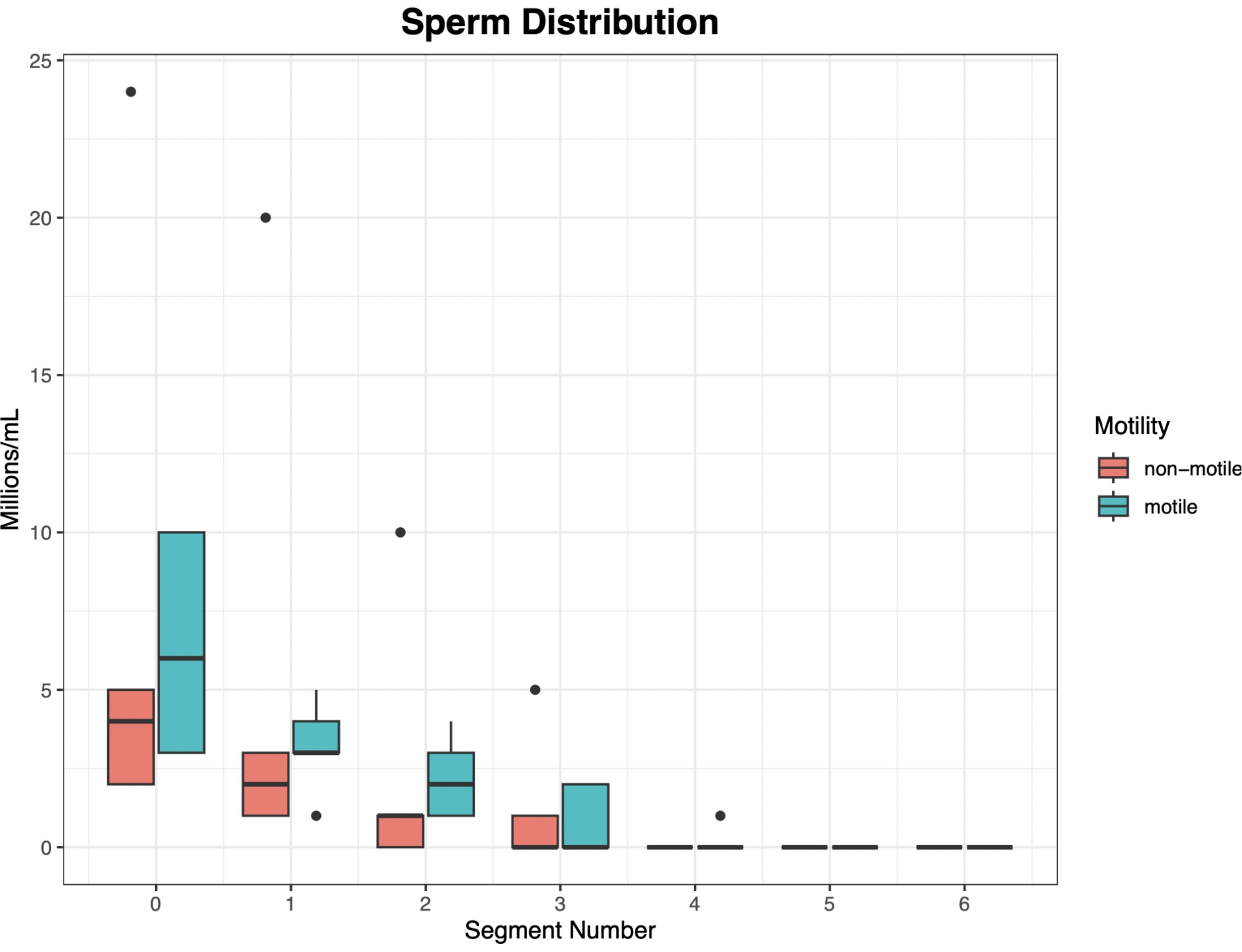
Figure 5. There is a clear decrease in the number of both non-motile and motile spermas you move further along the channel. X axis: segment number, where 0 is the segment between the waste and sperm input ports, 1 is the segment between the sperm input port and the first extraction port, and 2+ are the segments between extraction ports.
Next, we sought to determine whether the sperm present in the later segments were swimming faster than the majority located in the initial segments. To address this, we compared the straight-line velocity (VSL) and average path velocity (VAP) of sperm throughout the entire channel. Specifically, we analyzed data from videos of extracted aliquots and from videos recorded within the device (Figure 6a/b). Our analysis revealed a significant (p = 0.003 and p =1.53e-6, for VSL and VAP respectively) increase in both velocities in the sperm filmed within the device. Our linear model allows prediction of VSL and VAP based on segment number. Additionally, we observed a consistent increase in VCL (curvilinear velocity) and VSL across the channel, regardless of video source. Notably, the increase in VCL was more pronounced than the increase in VSL.
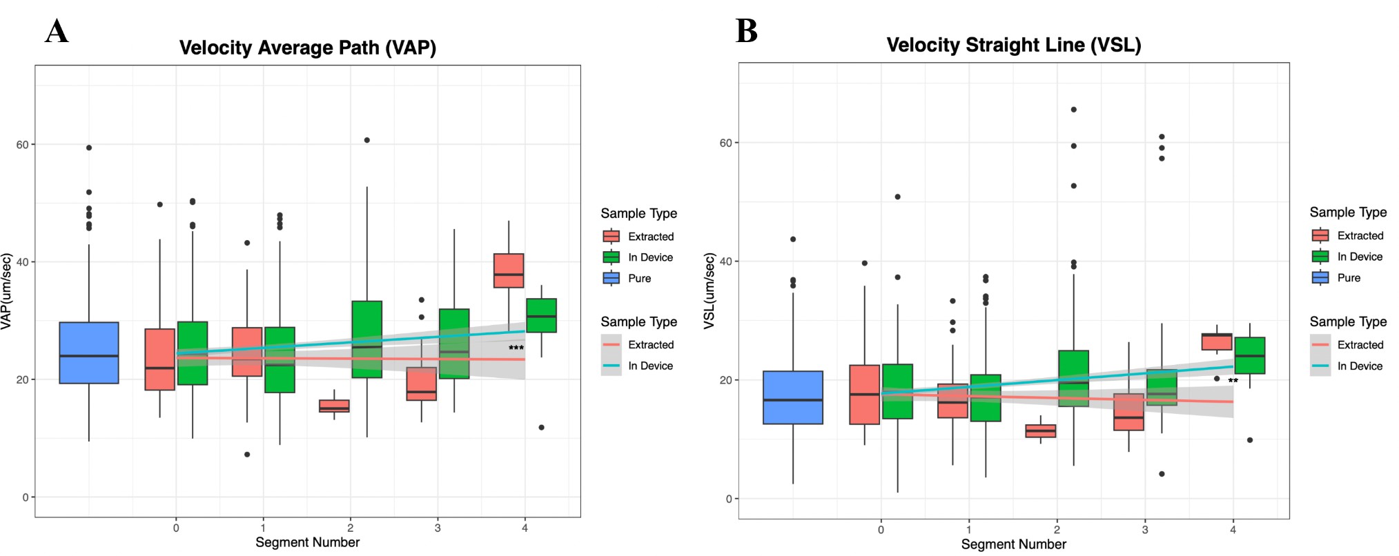
Figure 6. Sperm that traveled farther along the device swam faster. A) The VAP of both the data collected from the extracted aliquots and the in-device videos show a significant upward trend as you move along the segment. “Extracted” refers to sperm measured in a glass slide after extraction from the device, while “In Device” refers to sperm measured inside the device after the run was completed. “Pure” refers to sperm taken directly from the original sperm sample. B) The VSL shows a similar upward trend, but there is a less significant relationship between this velocity parameter and the distance swam along the segment.
Computer-Assisted Sperm Analyzer (CASA) provides further insights into sperm behavior outside of velocity parameters. One of these behaviors is the sperm’s linearity (LIN). We analyzed LIN using the same two video sources (extracted aliquots and in-device samples) as we did for VCL and VSL (Figure 7). The results were inconclusive: sperm from in-device videos exhibited a slight increase in linearity, while sperm from extracted aliquots showed a slight decrease. However, neither trend was statistically significant (p = 0.146 for in-device and p = 0.09 for extracted). Additional data and further analysis may clarify the relationship between linearity and the distance swum by sperm.
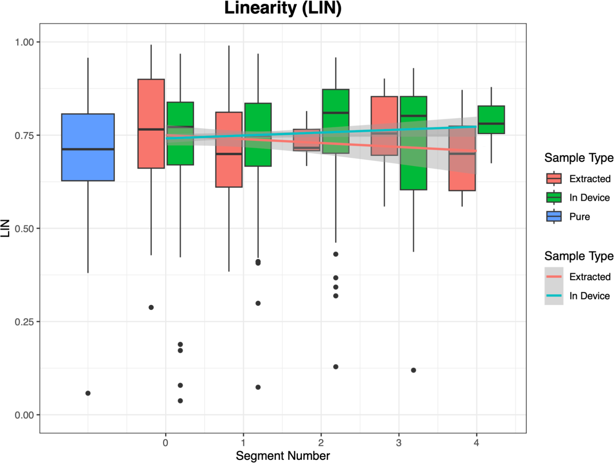
Figure 7. There is no significant relationship between linearity of sperm swimming and distance swam along the channel. This can be seen from the differing trend lines produced from the videos of the extracted aliquots and the videos from within the device.
Finally, we examined the characteristics of swimming for sperm in later segments, focusing on the wobble (WOB), or side-to-side head movement, and VCL across the channel in both video types (Figure 8a/b). Our results showed a significant increase in VCL in the later segments, indicating that sperm swam faster along curvilinear paths as they progressed. This suggests a potential relationship between the curvature of sperm movement without counterflow and their speed and distance when swimming with counterflow. WOB, however, showed an insignificant decrease along the channel (p = 5.50e-5), which contradicts the hypothesis that faster sperm show greater head wobble. Notably, the later segments in the racetrack contain fewer sperm (see Fig. 5), reducing the number of sperm measurements in the later segments. This may reduce our power to detect relationships between WOB and other sperm swimming metrics.
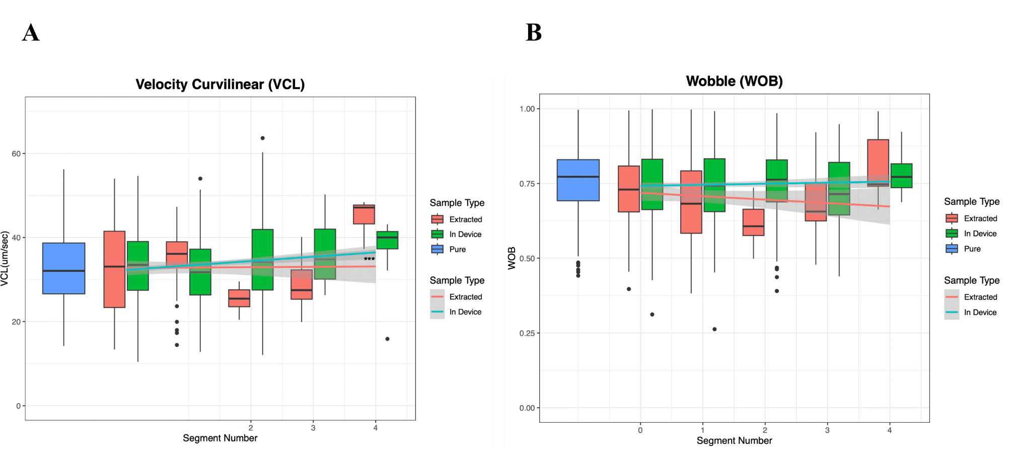
Figure 8. Curvilinear velocity increases along the channel, but not due to higher sperm wobble. A) There is a significant upward trend in the VCL as you move along the channel. This is true for both the data collected from the extracted aliquots and that from the videos taken in the device. B) There is a slight decline in WOB as you move along the channel, however it is insignificant.
These results indicate that the device presented is capable of effectively separating sperm based on their swimming speed via the induction of rheotaxis. However, interpretations for the behaviors responsible for the difference in swimming speed, such as wobble and linearity, are largely inconclusive.
Discussion
The aim of this study was to develop a biologically inspired microfluidic platform that can systematically sort a semen sample based on the speed of the sperm in a sample. In addition to sorting, the system must also offer a means for extracting the separated sperm. Current sperm-sorting methods, such as the swim-up and density gradient centrifugation, create reactive oxygen species that cause damage to the sperm cells. The Sperm Racetrack combats this damage and meets the additional design requirements by harnessing the biological behavior of sperm known as rheotaxis in a microfluidic environment and providing extraction ports to remove sperm post-sorting. We tested the microfluidic device with various semen samples and analyzed each extracted aliquot using the ImageJ plugin CASA. This measured both swimming speed and swimming behavior. The results of this analysis, in combination with a sperm count of each segment, indicate that the Sperm Racetrack is capable of separating sperm based on swimming speed.
The effectiveness of the microfluidic device is evident from the distribution of sperm across the device after sorting (Figure 5). The number of both non-motile and motile sperm decreases as they move further along the channel. This shows that sperm successfully traveled through the channel. Additionally, it confirms the device’s ability to separate sperm effectively, as fewer fast-swimming sperm (which travel farther) were observed compared to slower or non-swimming sperm.
In addition to the sperm distribution, the CASA analysis revealed key trends in sperm swimming behavior across each segment.
The first parameter, average path velocity (VAP), represents the point-to-point velocity of sperm along an average path calculated by an embedded algorithm in the plugin. As shown in Figure 6A, VAP increased significantly as sperm moved further along the channel in both videoed in-device samples and extracted samples. Another velocity parameter, straight-line velocity (VSL), measures the velocity between the first and last points on the sperm’s average path over the recorded time. Figure 6B shows a similar upward trend in VSL as sperm progressed along the channel, for both in-device and extracted samples. These correlations between VAP, VSL, and swimming distance confirm that the Sperm Racetrack effectively separated sperm based on swimming speed.
The final velocity parameter analyzed by CASA was curvilinear velocity (VCL), which measures the point-to-point velocity of sperm along their actual path over the recorded time. As shown in Figure 8A, VCL increased significantly with the distance swam along the channel.This demonstrates the microfluidic device’s ability to separate sperm by swimming speed and suggests a potential relationship between the curvature of sperm movement without counterflow and their speed and distance when swimming with counterflow. Further research is needed to explore this phenomenon.
CASA also provides insights into sperm swimming behavior beyond velocity parameters. One such parameter is wobble (WOB), which measures the intensity of a sperm’s side-to-side head movements. Figure 8B shows a slight decline in WOB as sperm move further along the channel, but this change is not significant. This suggests no clear relationship between side-to-side head movements and the distance swam. For example, non-progressive sperm with high WOB may fail to move past the first segment of the device.
Another parameter is linearity (LIN), which describes the straightness of a sperm’s swimming path. Figure 7 compares LIN trends for in-device and extracted samples. In-device samples show higher linearity due to counterflow, which causes sperm to orient upstream and swim more directly. Extracted samples, lacking counterflow, exhibit more circular swimming patterns and reduced linearity. Interestingly, the downward trend in LIN as extracted sperm moved further suggests a potential link between path straightness and swimming distance. However, the current data are insufficient to confirm this relationship. Further research is needed to investigate these observations.
While these results do indicate the success of the Sperm Racetrack, the device does still have limitations. The length of the channel in this version of the device is clearly too long, as the sperm fail to swim past the 4th segment. This could be shortened in future versions to reduce material costs. The straight nature of the channel is also limiting to the amount of sample that can be introduced into the device. Creating an injection ‘bowl’ or a circular portion of the device around the injection port may help to increase the amount of semen that can be introduced. This would allow for more sperm to be introduced, and thus more sperm to be extracted, making further testing, such as sequencing, more effective. Finally, the Sperm Racetrack protocol is very extensive. The operating time is long, and there are several steps in the testing protocol that require expertise and training to perfect.
Streamlining this protocol to make it simple for any individual to use would be the best way to overcome this limitation.
Despite these limitations, the Sperm Racetrack was effective in not only separating sperm based on swimming speed, but also in providing an extraction method for removing the sperm. This is evident from the presence of sperm in the sperm count data (Figure 5), as all sperm counts were taken from extracted aliquots. This extraction method makes this microfluidic device unique from existing devices that sort sperm based on speed in a microfluidic channel. While many utilize rheotaxis as a method for orienting the sperm and allow sperm to swim into different ‘segments’ based on their speed, [15-16], none of them have provided an effective method to extract the sperm for further genomic testing.
To conclude, we have designed, manufactured, and tested a device that separates sperm based on swim speed and allows extraction of sperm from the device in fast- and slow-swimming aliquots. We hope to use this device as a platform to delve into further genomic investigation into the mechanisms behind sperm swimming differences and explore the role these mechanisms play in male infertility.
References
- I. D. Sharlip et al., “Best practice policies for male infertility.”
- A. Agarwal, A. Mulgund, A. Hamada, and M. R. Chyatte, “A unique view on male infertility around the globe,” Reproductive Biology and Endocrinology, vol. 13, no. 1, Dec. 2015, doi: 10.1186/s12958- 015-0032-1.
- R. L. Verspoor, T. A. R. Price, and N. Wedell, “Selfish genetic elements and male fertility: Selfish genes and sperm,” Dec. 07, 2020, Royal Society Publishing. doi: 10.1098/rstb.2020.0067.
- L. Winkler and A. K. Lindholm, “A meiotic driver alters sperm form and function in house mice: a possible example of spite,” Chromosome Research, vol. 30, no. 2–3, pp. 151–164, Sep. 2022, doi: 10.1007/s10577-022-09695-4.
- N. Phadnis and H. A. Orr, “A single gene causes both male sterility and segregation distortion in Drosophila hybrids,” Science (1979), vol. 323, no. 5912, pp. 376–379, Jan. 2009, doi: 10.1126/science.1163934.
- S. Gupta and A. Kumar, “The Human Semen,” in Basics of Human Andrology, Springer Singapore, 2017, pp. 163–170. doi: 10.1007/978-981-10-3695-8_11.
- A. Zini, A. Finelli, D. Phang, and K. Jarvi, “INFLUENCE OF SEMEN PROCESSING TECHNIQUE ON HUMAN SPERM DNA INTEGRITY BASIC SCIENCE,” 2000.
- R. R. Henkel and W.-B. Schill, “Sperm preparation for ART,” 2003. [Online]. Available: http://www.rbej.com/content/1/1/108http://www.rbej.com/content/1/1/108
- G. M. Whitesides, “The origins and the future of microfluidics,” Jul. 27, 2006. doi: 10.1038/nature05058.
- S. M. Knowlton, M. Sadasivam, and S. Tasoglu, “Microfluidics for sperm research,” Apr. 01, 2015, Elsevier Ltd. doi: 10.1016/j.tibtech.2015.01.005.
- R. Samuel, H. Feng, A. Jafek, D. Despain, T. Jenkins, and B. Gale, “Microfluidic-based sperm sorting & analysis for treatment of male infertility,” Jul. 01, 2018, AME Publishing Company. doi: 10.21037/tau.2018.05.08.
- A. Jafek et al., “An automated instrument for intrauterine insemination sperm preparation,” Sci Rep, vol. 10, no. 1, Dec. 2020, doi: 10.1038/s41598-020-78390-3.
- H. Y. Huang, H. T. Fu, H. Y. Tsing, H. J. Huang, C. J. Li, and D. J. Yao, “Motile human sperm sorting by an integrated microfluidic system,” J Nanomed Nanotechnol, vol. 5, no. 3, 2014, doi: 10.4172/2157-7439.1000199.
- B. S. Cho, T. G. Schuster, X. Zhu, D. Chang, G. D. Smith, and S. Takayama, “Passively driven integrated microfluidic system for separation of motile sperm,” Anal Chem, vol. 75, no. 7, pp. 1671– 1675, Apr. 2003, doi: 10.1021/ac020579e.
- I. R. Sarbandi, A. Lesani, M. Moghimi Zand, and R. Nosrati, “Rheotaxis-based sperm separation using a biomimicry microfluidic device,” Sci Rep, vol. 11, no. 1, Dec. 2021, doi: 10.1038/s41598-021- 97602-y.
- S. Sharma, M. A. Kabir, and W. Asghar, “Selection of healthy sperm based on positive rheotaxis using a microfluidic device,” Analyst, vol. 147, no. 8, pp. 1589–1597, Mar. 2022, doi: 10.1039/d1an02311j.
- Z. Zhang et al., “Human sperm rheotaxis: A passive physical process,” Sci Rep, vol. 6, Mar. 2016, doi: 10.1038/srep23553.
- V. Kantsler, J. Dunkel, M. Blayney, and R. E. Goldstein, “Rheotaxis facilitates upstream navigation of mammalian sperm cells,” Elife, vol. 3, May 2014, doi: 10.7554/elife.02403.
- B. M. Carlson, “The Reproductive System,” in The Human Body, Elsevier, 2019, pp. 373–396. doi: 10.1016/B978-0-12-804254-0.00014-4.
- Wilson-Leedy JG, Ingermann RL. Development of a novel CASA system based on open source software for characterization of zebrafish sperm motility parameters. Theriogenology. 2007 Feb;67(3):661-72. doi: 10.1016/j.theriogenology.2006.10.003.
