College of Mines and Earth Sciences
75 Precocious Scaphites and the Hydrodynamic Consequences of the Development of Ribbing
Garrett Butler; Kathleen Ritterbush; Nicholas Hebdon; Mikelia Heberer; David Peterman; and Junji Choi
Faculty Mentor: Kathleen Ritterbush (Geology and Geophysics, University of Utah)
Abstract
Basic conch geometry roughly constrains how different ammonites could balance and swim. But it remains unclear what costs – or advantages – are added by complex ribbing and other conch ornamentation. We present a case study with juvenile scaphite ammonites from the Western Interior Seaway of the Late Cretaceous. Scaphitid conchs typically change shape considerably through ontogeny. Juvenile planispiral conchs offer varied streamlining that reduces drag resistance when swimming. Adult conchs produce a hook-shaped body chamber that forfeits streamlining for hydrostatic stability. Ribbing, however, for many species persists throughout an individual’s life with little change in amplitude and wavelength. We weigh the hydrodynamic cost of ribbing in these juvenile conchs using computational fluid dynamic simulations (CFD). We create synthetic scaphitid 3D models of two representative shapes from specimens collected in the Upper Cretaceous Pierre Shale: an inflated discocone and a moderately compressed oxycone. We add simple ribs to each, for a total of four test cases. Flow simulations target a series of velocities from 1-20 cm/s on specimens 4-5 cm in diameter.
Generally, an inflated conch shape generates more overall drag force than a compressed shape. Ribs, meanwhile, cause an inflated specimens yield drag force to be closer to those of a compressed specimen. We interpret this as a consequence of premature shear experienced at the ribbing interface along the conch flank, and at the umbilical shoulder. For juvenile scaphites, inflation and ornamentation cause opposing trade-offs in drag force with increasing turbulence. If our ammonites were traveling slower than one body-length per second (or were smaller in size), compression and/or ribbing exacerbate drag force. If our ammonites were traveling faster than one body-length per second (or were larger in size), compression and/or ribbing reduce drag force. Between two individuals, the inflated form should favor maneuverability and acceleration, while the compressed form should travel greater distance for the same effort.
Ribbed ornament appears to help the inflated conch behave more like a compressed conch. Collectively, juvenile scaphites appear to occupy every position within a highly constrained maneuverability-efficiency-speed landscape.
Introduction
Ammonoid conchs with a spiral shape also feature many different styles of ornamentation, including ribs, nodes, tubercles, and spines. Possible functions of these morphological distinctions might relate to defense, sexual maturity, hydrostatics, or hydrodynamics. Here, we examine possible hydrodynamic consequences of ribbing with a simple test: do we see increase (or decrease) in swimming efficacy due to ribbing in juvenile scaphitd ammonoids from the Western Interior Seaway? We do not address developmental origins of ribbing structure, but rather contribute to a broader vision: an adaptive landscape analysis of ribbing. Overall, we find that there is a non-linear relationship between ribbing and efficiency, and highlight a marked reduction of negative pressure in compressed conchs. The development of ammonoid conch ribbing has long been regarded as a process of defense against breakage from predator attacks (Ward 1981). From first principles, however, complex surfaces should impact the underwater motion of ammonoid-sized objects. Drag coefficient is a function of velocity, direction of flow, object position, and shape and size (Mallick 2016). Work on cylindrical objects shows that applying a rough surface decreases the coefficient of drag while increasing the force of drag (Mallick 2016). Past efforts have been made to link morphological distinctions to ecospace occupation. The Westermann Morphospace method allows for a quantitative analysis of growth ratios to diagram morphotypes (Ritterbush and Bottjer 2012).
Orientation of ammonoids in a hydrostatic and hydrodynamic setting is complex. The hydrostatic setting of scaphites has been researched extensively and has found that juvenile scaphites differed very little from the adult heteromorphs (Peterman 2020). This work also determined that front to back rocking is minimized in scaphitid ammonoids due to their mass distribution (Peterman 2020). Drag coefficient has been extensively examined in relation to the width growth ratio. Work completed on this subject found that shell inflation and umbilical exposure influence the hydrodynamic efficiency through a reduction of the coefficient of drag (Hebdon 2020). This work also outlines the process and tests the efficacy of CFD simulations in an ecological setting. By testing idealized Nautilus shells with experimental data using live Nautilus (Hebdon 2020). In separate work, this team has completed a Westermann Morphospace of smoothed specimens at various velocities. This work also found that the inflation ratio has major consequences for coefficient of drag (Hebdon 2020). This workflow begins with a collection and statistical analysis of planispiral schapitid ammonoids. Accurate 3D representative models are then designed using measured growth ratios of a given specimen. Basic, non-sinuous ribbing structure is then applied logarithmically around the exposed surface of the shell for analysis of the hydrodynamic consequences of ribbing and inflation. 3D models are then generated as CAD models within Ansys for use in computational fluid dynamics (CFD) such that ornament detail is not lost.
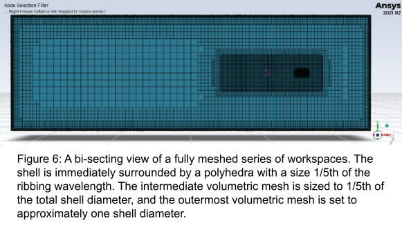
Simulation architecture is implemented to balance a high resolution area surrounding the shell while reducing the total computational demand. A mesh is then generated using a polyhedra type mesh with the smallest polyhedra diameter 1/5 the ribbing wavelength (ribbed specimen) or umbilicus diameter (smoothed specimen). CFD simulations are prepared and set to 500 iterations for collection of measured data. Measured data is then used for various calculated data to be plotted against Reynolds Number within the computer program R.
Methods
The collection of well preserved juvenile scaphitid ammonoids were chosen for their planispiral morphology and completeness of a 180deg section of conch. Twenty-eight specimens were measured by their various shape ratios (inflation, umbilicus diameter, aperture height) to be examined in a Westermann Morphospace Analysis (Ritterbush and Bottjer 2012). The specimens range in shape from spheroconic to oxyconic (Figure 1).

The specimens chosen for further analysis represent the distinct variants within this sample: one inflated and one compressed specimen. Measured growth ratios of the chosen specimen are then applied to the computer program “The Shell GeneratorV2” by Olivia Jenkings. “The Shell GeneratorV2” creates accurate 3D models using measured growth ratios in the file type stereolithography (.stl) for low file size and general use in 3D modeling programs. (Figure 2)
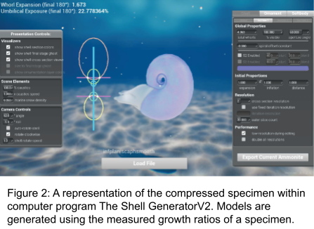
“The Shell GeneratorV2” also allows for use of “UV Skinwraps”, that are applied logarithmically along the surface of the model which allows for the addition of iterative ammonoid ornament.
We used the open source 3D computer graphics program “Blender” to further prepare models for use in CFD. Synthetic soft bodies are created and sized to be 20% of the total diameter. This is done to eliminate large amounts of vortex drag from occurring at the otherwise flat aperture face of the conch. (Hebdon 2020) Four initial models were made with each the inflated and compressed specimen represented by a smooth and ribbed model. (Figure 3 B-C)
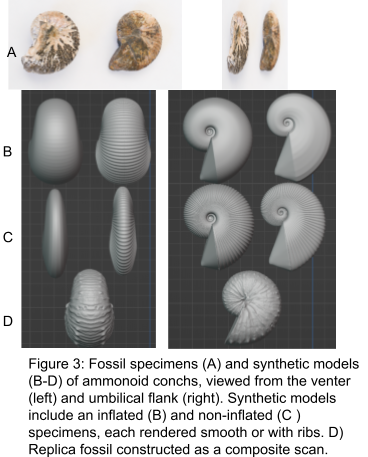
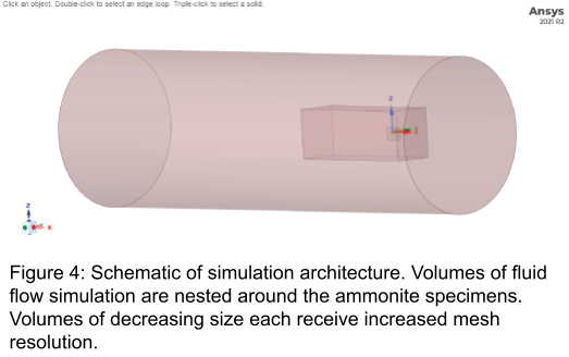
A fifth model was made using a complete quarter whorl generated from a 3D scan of a physical specimen using the Array modifier has yet to be further tested. (Figure 3 D) Models undergo three modifiers to limit computational demand while maintaining resolution of umbilicus and ribbing. A triangle count of approximately 300,000 is targeted and models are then exported as .stl files. The multiphysics engineering simulation software Ansys is used for the generation of CAD models of specimens and further analysis of steady state fluid dynamics. The Fluid Flow (Fluent with Fluent Meshing) has four primary sections; geometry, meshing, set-up, and results. The first section, geometry, is used to generate a CAD model and to create “workspaces”. CAD models are made using a skinwrap tool set to parameters of a 0.1mm gap size and 6° angle threshold. Workspaces are cylinders/rectangular prisms made to create various areas of increasing size with decreasing resolution surrounding the shell model to balance desired data resolution with computational capabilities. (figure 4).
Finished simulation schematics are then exported through Ansys to the next section, meshing. The meshing section is utilized to create a polyhedra type mesh of increasing polyhedra diameter for each workspace. Polyhedra diameter for the smallest workspace is chosen by taking 1/5 the measurement of the smallest detail desired to be analyzed. For smooth specimens 1/5 the umbilicus diameter was used and 1/5 of the ribbing wavelength for the ribbed specimens. (figure 5)
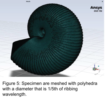
The intermediate workspace is meshed with a polyhedra diameter of 1/5 of the total diameter of the shell. The final workspace is sized using the full diameter of the shell. The meshing process is used to apply characteristics to the various regions created within geometry. The shell CAD model is used as a “body of influence” relative to the workspaces. The CAD model is described as “dead space” and the workspaces as regions for fluid flow. When meshing information is successfully set up a mesh can be generated and exported into the “set-up” section. The Set-Up section is utilized to prepare the meshed import for the process of iterative physical computational analysis. Set-up is used to communicate the user’s chosen parameters for future simulations. This includes; flow velocity, fluid density, etc. Profiles can be created to create output variables from force vectors. Force of drag and viscous shear stress relative to frontal fluid impact face are used for the scope of this analysis. Set-up is also used to determine how many iterations Ansys will calculate for any flow velocity. A 500 iteration minimum was used for each calculation and velocities ranging from 1/8 to 8x the body length. An increment of 1/2 times the body length was used. This data is then visually represented in the Results section using tools such as a planar vector profile and isosurface generation. (Figure 6 & 7)
Data is physically represented within the Parameters tab as tabled values which can be readily prepared as a .csv file for analysis in the statistical computing and graphics software, “R”. R Core Team 2021) R is used to calculate values of the total coefficient of drag, separating various coefficients relating to drag (viscous, pressure) and for plotting data. Coefficient of drag is calculated using Equation 1.
Equation 1. 𝐶𝑑 = (2 ⋅ 𝐹𝑑)/(𝐴 ⋅ 𝜌 ⋅ 𝑈 2 ) where A is the cross-sectional area relative to the YZ plane and Fd is the force of drag calculated using Ansys. The coefficient of viscous drag is calculated using Equation 2.
Equation 2. 𝐶𝑣 = (2 ⋅ 𝑉𝑠𝑠)/(𝑎𝑟𝑒𝑎 ⋅ 𝜌 ⋅ 𝑈 2 ) with the viscous shear stress in the x direction denoted as Vss. The same cross-sectional area is used for A, density as rho, and velocity as U. The coefficient of pressure drag is calculated using Equation 3.
Equation 3. 𝐶𝑝 = 𝐶𝑑 − 𝐶𝑣 The calculated coefficients of drag are then plotted against Reynolds Number, the ratio of inertial forces to viscous forces. The Reynolds Number is calculated using Equation 4.
Equation 4. 𝑅𝑒 = (𝑆ℎ𝑒𝑙𝑙 𝐿𝑒𝑛𝑔𝑡ℎ ⋅ 𝑈)/𝑣 Here the velocity is denoted by U and liquid viscosity is denoted by v.
Results
Plotting separated coefficients of drag against Reynolds Number compares the varied impact that ribbing or inflation has. Coefficient of pressure drag and the coefficient of viscous drag have been calculated using Equations 1 & 2 from the total coefficient of drag.(Figure 8)
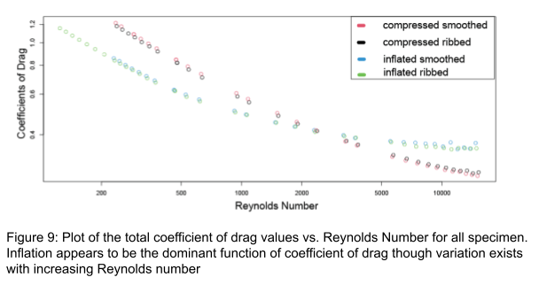
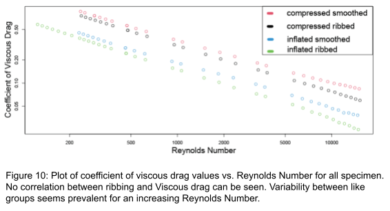
Here, each specimen; compressed smoothed, compressed ribbed, inflated smoothed, and inflated ribbed will be denoted as CS, CR, IS, and IR respectively. By comparing the positions of each specimen along the various drag coefficient plots allows for analysis of the impact on ribbing relative to inflation. For coefficient of viscous drag it is clear that inflation dominates the system as shown by clumping of CS & CR vs. IS and IR with an order from top to bottom of CS, CR, IS, IR. (Figure 9)
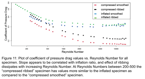
Coefficient of pressure drag differs from these results dramatically. At low Reynolds Numbers an overlap between IS & CR coefficient values highlighting the overall effect of ribbing. With increasing turbulence comes an overall reduction of coefficient values, compressed specimens experience a greater decrease until a Reynolds number of approximately 2000. This demonstrates that the overall effect of ribbing is more intensive for specimens with a decreased inflation ratio. (Figure 10)
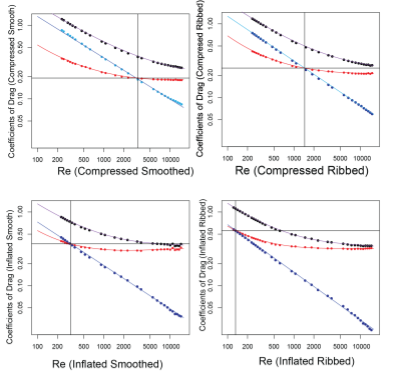
These results are supported further by plotting each individual specimen’s various coefficients of drag plotted against Reynolds Number. (Figure 11)
Plotting data in this way allows for analysis of a crossing point between a system dominated by viscous drag vs. a pressure drag. It is clear that the overall effect of ribbing or inflation on viscous drag has very little effect on the total system as the coefficient of viscous drag changes very little in slope and prospective y-intercept. Instead, each specimen varies greatly only in coefficient of pressure drag. Regardless of inflation the point in which the system changes from a viscous drag dominated system to one of pressure drag is decreased by approximately one-half of the Reynolds Number of the smoothed version. Furthermore, the crossing point is reduced by more than one-half in the case of the compressed specimen supporting the idea of greater impact with reduced inflation. (Figure 12)
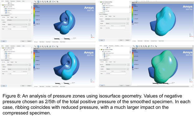
Visual nuances within analysis of pressure values using Ansys tools; isosurface volume, and planar surface allow for a more distinct interpretation of computational data. (Figures 6 & 7) Positive pressure zones occur where water is being displaced by the mass of the shell in front of the point of contact and does not change with the addition of ribbing, instead increasing with a larger inflation. Negative pressure zones decrease in magnitude for each, the compressed and inflated specimen with the addition of ribbing. This reduction is greatest near the umbilicus and is larger for the compressed specimen.
Discussion
The data presented shows a consequence on the hydrodynamic characteristics of ammonoids due to the development of a simple ribbing structure. This data is not sufficient enough to rank the importance that hydrodynamics has on the development of ribs relative to other causes for development. However, ribbing does have a measurable effect on how a shell experiences drag while swimming. The magnitude of effect from ribbing is related to the inflation ratio of a specimen. These factors allow for the use of ribbing structures to be used within an adaptive landscape statistical analysis of ammonoids to better understand the ecological impacts of morphological distinctions. A possible result may be that compressed specimens develop ribbing preferentially relative to inflated specimens in a similar environment due to the overall effect of inflation. This may also lead to ribbing amplitude being on average lower than an inflated counterpart within an environment. This study does not provide conclusive reasoning for the fundamental physics that underlie the cause of a reduction of the coefficient of drag. Speculative reasoning surrounds the concept that ribbing structures increase the rate of vortex shedding. Kármán vortex streets are formed due to the conditions of the boundary layer of rigid body surfaces. Vortices form as water nearest to the conch is slowed relative flow further from the shell. Vortices from each side form together to pull the object back. The capability to reduce vortices through vortex shedding results in a reduction of vortex drag. Ribbing may induce vortex shedding by directing water by channeling flow through ribs parallel to flow, or skipping water over ribs that are perpendicular to flow. The disruption of water flow immediately surrounding a rigid body reduces the unified flow of vortices which slows their oscillatory constructive progression. The impact of parallel ribbing as compared to perpendicular ribbing is unknown. This claim is supported by the use of isosurface generation of turbulent kinetic energy values within Ansys. (Figure 13)
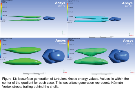
By selecting large values of turbulent kinetic energy Kármán vortex streets can be visualized as they form behind the conch. For each the compressed and inflated specimens a reduction in the clarity or definition of these Kármán vortex streets can be seen with the addition of ribbing. The future goals of this project consists of three primary goals; (1)idealizing a workflow for generating “clean” CAD models from whorl sections of 3D scans, (2)collecting data on end member groups growth ratios relative to the Westermann Morphospace for a wider study of ammonoid groups, (3)and generating models utilizing a variety of ribbing structures.
- The use of 3D scans within CFD remains difficult due to taphonomic pressure. Specimens that are considered well preserved often have extensive damage that would affect the examination of hydrodynamic properties. Idealizing the process of generating a synthetic model using an array modifier within Blender on the best preserved section allows for the best representation of complex ornamentation due to the difficulty of mimicking these structures.
- This study focused on ammonoid specimens ranging between oxyconic and spheroconical end-members. By analyzing a wide variety of specimens on a range of Westermann Morphospace growth ratio values we can further examine the hydrodynamic consequence of ribbing. We can compare effects of growth ratios as well as evoluteness of ammonoids, that is umbilical exposure, as they relate to the effect change from ribbing.
- While a simple ribbing structure such as is used within this study allows for a simpler process of examination. Analysis of the complexity of the ornamentation of ammonoids including; ribbing, nodules, and keels that are representative of a true species may allow for a more distinctive conclusion. This may allow for a clear positive relationship between an increase in complexity of ornamentation and hydrodynamic consequence to be determined.
The secondary goals are as follows; Isolate the coefficient of vortex drag from the coefficient of pressure drag, and begin developing an adaptive landscape through statistical analysis of data. Each of these goals necessitate extensive data collection and thusly will remain long term goals.
Conclusion
We find that for each test case, the threshold for a system dominated by viscous vs pressure drag forces occurs at reduced levels of turbulence represented by Reynolds Number. Visual representations of pressure values using 2D and 3D modeling within Ansys supports these findings and highlights a reduction in negative pressure values. Negative pressure is reduced surrounding the umbilicus shoulder and behind the shell, the effect of reduction is greater for compressed specimens as compared to inflated specimens.
Acknowledgements
We would like to thank Tom Linn for the generous support in our collection of specimens and genuine hospitality. TJ Ferril, Tony Sams and the rest of the staff in the Protospace at the Marriott Library for providing a place to meet and a space to use for collaboration of research. The Undergraduate Research Opportunity Program and the Geology and Geophysics department at the University of Utah for their continued support in our work.
Bibliography
Ward, P. (1981). Shell sculpture as a defensive adaptation in ammonoids. Paleobiology, 7(1), 96- 100
Mallick, Monalisa. (2016). VARIATION OF DRAG COEFFICIENT ON ROUGH CYCLINDRICAL BODIES. 10.13140/RG.2.1.3202.3926.
Ritterbush, K. A., & Bottjer, D. J. (2012). Westermann Morphospace displays ammonoid shell shape and hypothetical paleoecology. Paleobiology, 38(3), 424-446.
Peterman, D. J., Hebdon, N., Ciampaglio, C. N., Yacobucci, M. M., Landman, N. H., & Linn, T. (2020). Syn vivo hydrostatic and hydrodynamic properties of scaphitid ammonoids from the US Western Interior. Geobios, 60, 79-98.
Hebdon, N., Ritterbush, K., & Choi, Y. (2020). Computational fluid dynamics modeling of fossil ammonoid shells. Palaeontologia Electronica.
Hebdon, N., Ritterbush, K., & Choi, Y. (2020). Assessing the morphological impacts of ammonoid shell shape through systematic shape variation. Integrative and Comparative Biology, 60(5), 1320-1329.
R Core Team (2021). R: A language and environment for statistical computing. R Foundation for Statistical Computing, Vienna, Austria. URL https://www.R-project.org/.
