4 Example 2-1 Envelope Calculator
“Focused View” Simulation link:
Ω
APP THUMBNAIL TODO ADD!:
[add envelope calculator envelope here]
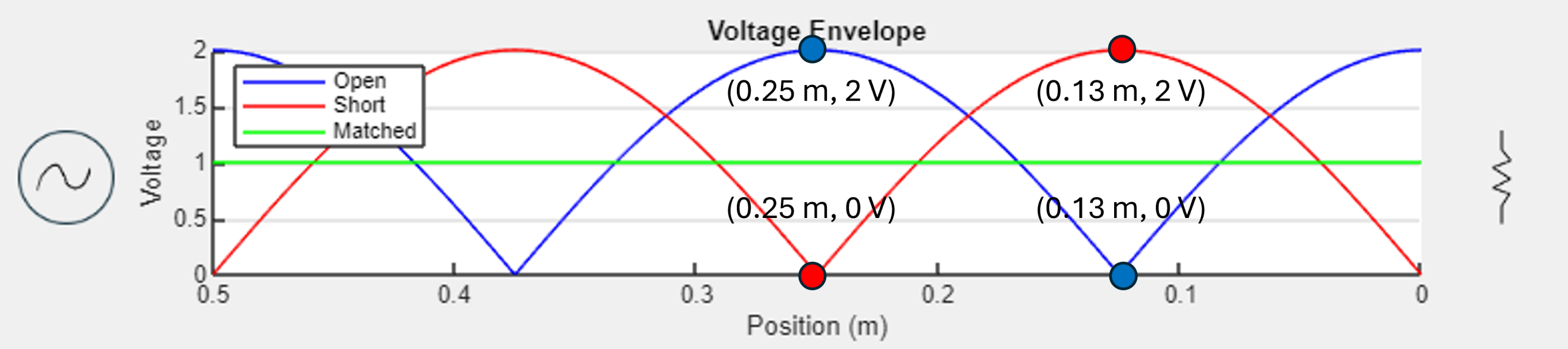
IN TEXT DESCRIPTION: Figure [??] illustrates how an open, short and matched load affect the envelope for a simple 1 V amplitude sinusoidal signal on a 50 Ω transmission line. The signal source is indicated on the left and the load on the right. Recall that for transmission lines, distance is measured from the load and not from the source. The y-axis is, then, not the location of the source.
The open load’s envelope has a maximum of 2 V at the load itself and the short load’s envelope has a minimum of 0 V. Note that the nodes of the open load are the antinodes of the short load. The matched load’s envelope is a constant 1 V across the entire transmission line since there is no reflected energy. For an interactive version, go to the envelope calculator app.
IN TEXT DESCRIPTION:
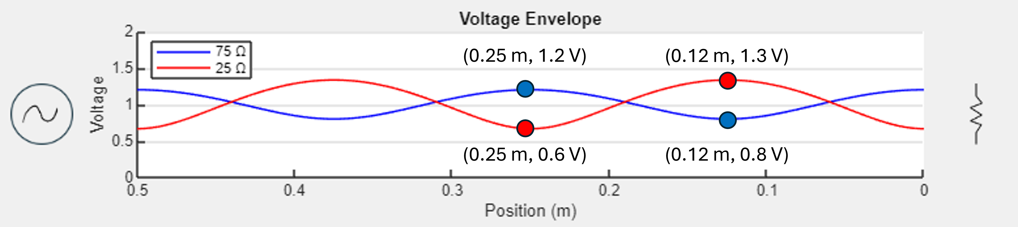
Figure [???] below shows how a 75 Ω and 25 Ω load affect the envelope. Note that since 75 Ω is greater than 50 Ω, the resulting reflection coefficient is positive whereas for the 25 Ω load the reflection coefficient is negative. This yields a higher envelope at the load for 75 Ω than does 25 Ω. Since neither of these loads yields a maximum reflection coefficient, the envelopes do not indicate a pure standing wave since only some of the energy is reflected from the load. For an interactive version, go to the envelope calculator app.
Media Attributions
- OpenShortMatchedEnvelopes
- 75 and 25Ohm Envelope
