The Equivalent Circuit Model of the Neuronal Membrane
Cody Zundel and Jim Hutchins
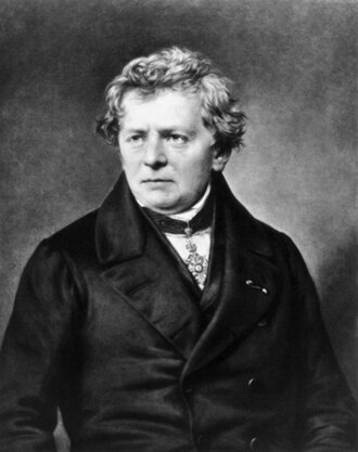
Some of you may have been introduced to Ohm's Law in other classes, such as physics or electrical engineering. Ohm's Law is a simple mathematical relationship between three quantities:
- voltage, a measure of electrical potential energy;
- current, a measure of electrical current flow; and
- resistance, how difficult it is to get electric current to flow.
In a wire, current is carried by a moving wave of electrons is created at one end of a copper wire, and that moving wave spreads at near-light speed through the wire, carrying current as it goes.
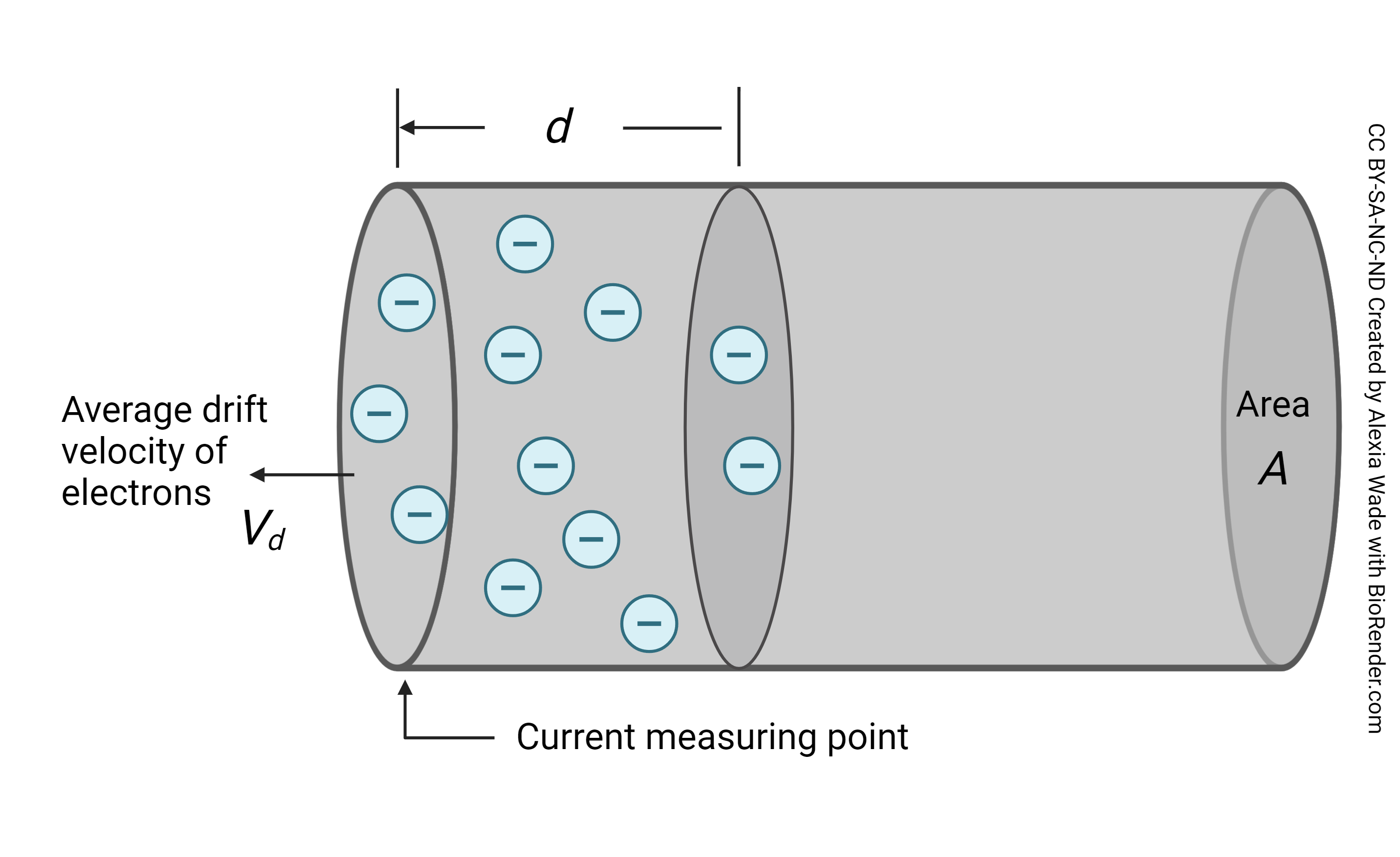

In this wire, voltage is the force that impels electrons to move from one end of the wire to the other. Voltage is a measure of electrical potential energy. Potential energy is the energy that will push electrons (or charged particles, like sodium or potassium ions) once they are allowed to move. An analogy: potential energy for water is measured by the height of a water tank above the town, before a valve is opened that allows the water to flow.
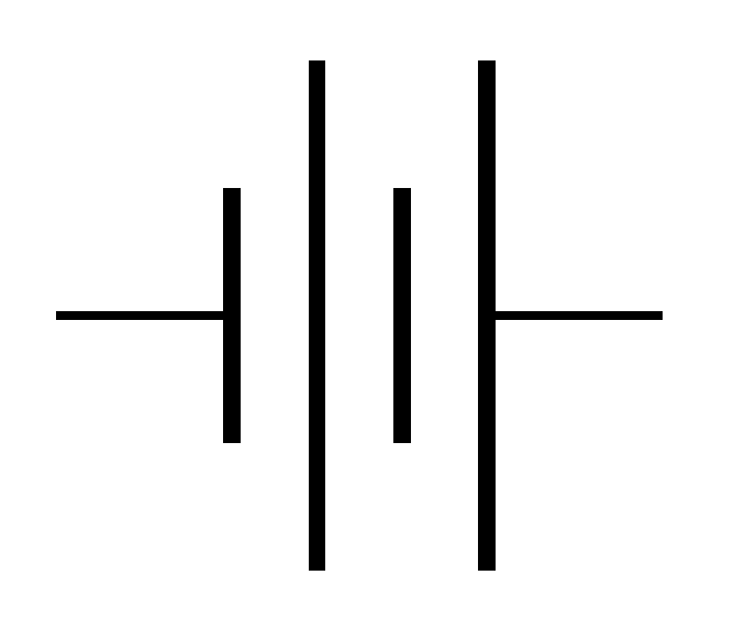
Batteries supply voltage. You know this already; you have probably noted the voltage on a battery (e.g. 1.5 V AAA battery; 9 V battery) without thinking about this much. For a neuron, the "battery" which supplies voltage is the difference between the membrane potential and the equilibrium potential for that particular ion. To take one example, if the membrane voltage (Vm) is –70 mV, and the equilibrium potential for sodium (ENa) is +60 mV, then the voltage due to sodium (VNa) is 130 mV.
Current is electrical kinetic energy. This is the movement of charged particles (electrons, Na+, K+, etc.) — how many particles move past a single point over a fixed time? The SI definition is 1 coulomb of charge per second, or 6.241509×10¹⁸ charges moving per second.
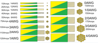 Resistance, as the name implies, is a measure of how difficult it is for charges to flow. It is more difficult for electrons to flow through a tiny, thin wire than through a huge, thick wire. This is encompassed in the wire gauge chart shown here: note that large wires carry significantly more current (in amperes) than small wires. Similarly, small pipes carry less water per minute than large pipes. We see the same in nerve axons: large axons offer less resistance to current flow than small axons.

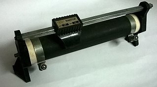
The symbol for a resistor is a zigzag line. If the resistance can be changed (a variable resistor), then an arrow is drawn through the line to indicate a dial or knob that is changing the resistance. A rheostat, a type of variable resistor, looks much like the symbol for a variable resistor. Here, a sliding box moves along a spiral wire and the path taken by electricity is lengthened or shortened as one slides the box. (Resistance is a function of the length of the electrical path.)
Finally, there is a quantity not found in Ohm's Law but important to neuroscientists: conductance, or g. Conductance is simply the inverse of resistance, 1/R. In the chart above, the large wires have a higher conductance than the small wires.
Ohm's Law is the relationship between voltage (V), current (I) and resistance (R):
[latex]\quad V = IR[/latex]
[latex]\text{if} \quad g = \frac{1}{R}[/latex]
[latex]\text{then}\quad gV = I[/latex]
Now we are ready to take these concepts, and their symbols, together into an equivalent circuit model of the neuronal cell membrane.
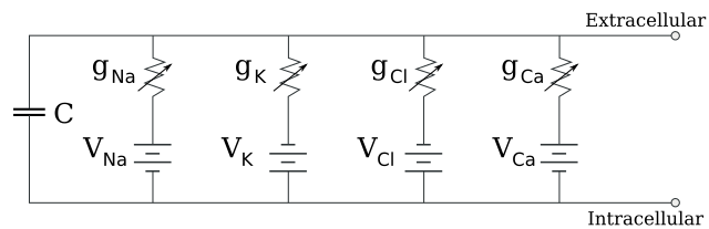
Potential energy (voltage) is supplied by the difference in electrical potential for each ion between the outside and inside of the membrane. For example, sodium is at high concentration outside and wants to move from outside to inside, but is constrained from doing so. The potential energy (voltage, V) for each ion is shown as a battery with a series of short and long parallel lines: VNa, VK, VCl, and VCa.
The direction of the battery plates in this diagram is important. Note that the smaller parts of the sodium battery (VNa) and calcium battery symbol (VCa) are oriented towards the inside of the cell. That means that Na+ and Ca2+ will flow into the cell if they are allowed to flow. The smaller parts of the VK and VCl batteries are oriented towards the outside of the cell. Because K+ has a positive charge, it will flow towards the smaller plate on the battery symbol, i.e. out of the cell. Because Cl– has a negative charge, it will flow towards the larger plate on the battery symbol, i.e. into the cell.
The channels which allow ions to flow are shown, collectively, as a variable resistor (a zigzag line with arrow through it). As we have seen previously, there are various sorts of ion channels with various properties which allow ions to flow across the cell membrane. The collective action of sodium channels to allow sodium to flow through the membrane is shown as gNa. There are also potassium channels, chloride channels, and calcium channels (gK, gCl, and gCa).
 The two parallel lines marked "C" represent a new electrical property, not found in Ohm's Law, called capacitance. A capacitor is a pair of electrically-charged plates separated by a dielectric (i.e., a substance which resists current flow). A cell membrane, including the neuronal cell membrane, is two charged surfaces (the polar heads of phospholipid molecules facing the outside and inside of the cell) separated by a dielectric (the non-polar, uncharged tails made up of insulating lipid).
 This model of the neuronal membrane was proposed in a landmark 1952 paper by Alan Hodgkin and Andrew Huxley based on their experiments with a giant axon from the squid Loligo. This paper was the fifth and last in a series which used this model system. Because this axon is 500 times larger in diameter than a mammalian axon, it was large enough to introduce a fine wire directly.
The only part of this equivalent circuit which was known to Hodgkin and Huxley was the battery, or electromotive force for each ion, which was well-established by the middle of the 20th century. Direct electrophysiological evidence from the 1930s supported what Walther Nernst constructed theoretically as the equilibrium potential.
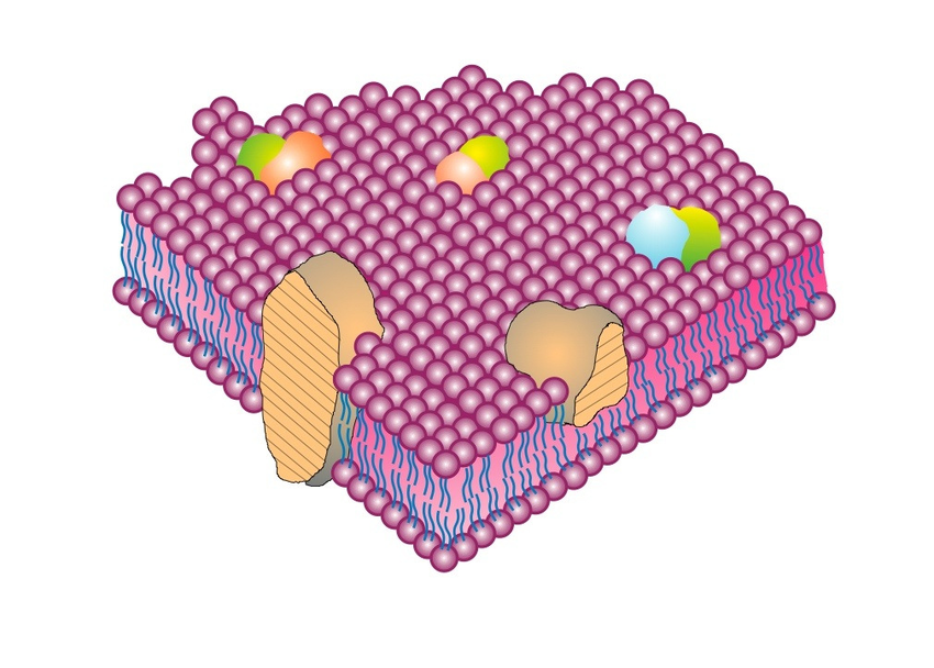
The rest of the equivalent circuit model was theory when Hodgkin and Huxley published their findings. Amazingly, this purely theoretical idea was validated in thousands of subsequent experiments, including the Singer-Nicholson fluid mosaic model of the cell membrane (1972), which proposed that protein "icebergs" float in the membrane bilayer "sea". This observation validated the capacitor, C, in the Hodgkin-Huxley equivalent circuit model.
Still, the nature of the protein channels waited to be elucidated by the patch clamp method, discovered in 1974 by physicist Erwin Neher and cell physiologist Bert Sakmann at the Max Planck Institute for Biophysical Chemistry in Göttingen, Germany. The variable resistors are now known to be different types of protein channel.
The equivalent circuit model, and the mathematical analyses it makes possible, open the door for a number of further applications:
- Membrane potential dynamics: this model allows us to understand how the membrane potential changes over time in response to stimuli.
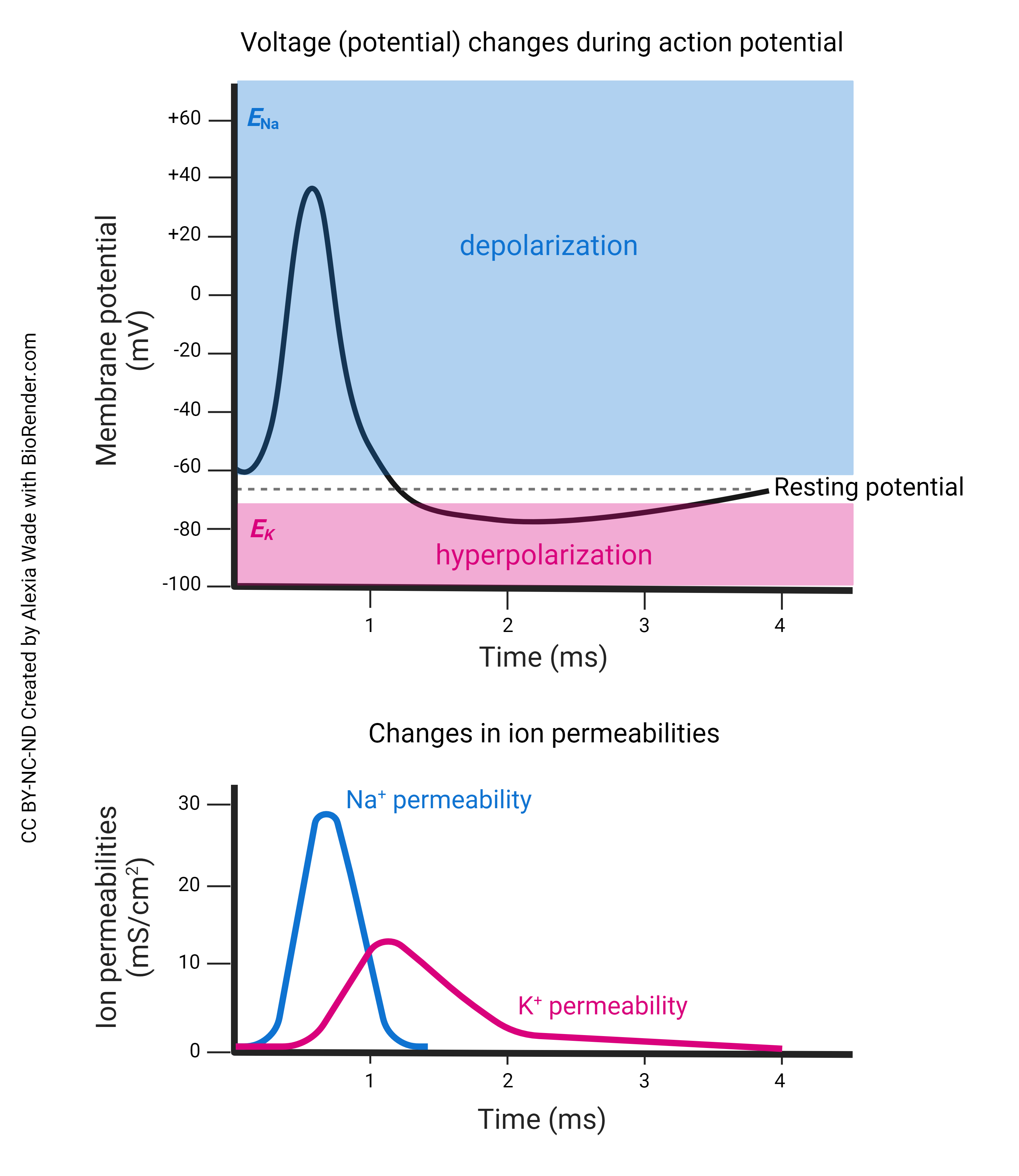
- Modeling the action potential: as Hodgkin and Huxley realized, the action potential can be modeled by changing the flow of ions through the variable resistors in a characteristic pattern.
- Computational Neuroscience: the equivalent circuit model is used in computer simulations to study complex neuronal networks and their behavior.
- Software tools: programs like NEURON and NEST use this model to simulate the electrical activity of neurons and networks.
- Neuroprosthetics: understanding the electrical properties of neurons aids in developing devices like cochlear implants and brain-machine interfaces.
- Disease modeling: this model allows simulation of pathological changes in membrane properties in diseases such as epilepsy and neurodegenerative diseases.
- Brain-Computer Interfaces: informs the design and optimization of brain-computer interfaces (BCIs), which rely on understanding and coupling to neural electrical activity.
- Neural modulation: techniques such as deep brain stimulation use insights from the equivalent circuit model to optimize stimulation parameters to achieve the desired therapeutic effect.
- Pharmacological testing: for drugs that bind to ionotropic receptors, predict how different drugs will affect neuronal activity by altering the resistance (conductance) of each ion described in the model.
- New therapies: an understanding of how changes in conductance affect neuronal function may illuminate new therapeutic strategies.
Media Attributions
- Peach © Jim Hutchins is licensed under a CC BY-SA (Attribution ShareAlike) license
- Battery symbol 69SVs © Hans, LaTeX Stack Exchange is licensed under a CC0 (Creative Commons Zero) license
- Water © Joe Pell is licensed under a CC BY (Attribution) license
- Wire size grounding conductors © Powerfox is licensed under a CC BY-SA (Attribution ShareAlike) license
- Variable resistor symbol © K. Bolino is licensed under a Public Domain license
- Reostat-control electric current © Kvr.lohith is licensed under a CC BY-SA (Attribution ShareAlike) license
- Georg Simon Ohm © Unknown is licensed under a Public Domain license
- Cell membrane equivalent circuit © Arne Nordmann & Looie496 is licensed under a CC BY-SA (Attribution ShareAlike) license
- Screenshot 2024-07-21 130543
- Capacitor Symbol © Jjbeard is licensed under a Public Domain license
- Screenshot 2024-07-21 131857 © AL Hodgkin & AF Huxley is licensed under a All Rights Reserved license
- The-Singer-Nicolson-Fluid-Mosaic-Membrane-Model-of-cell-membrane-structure-as-proposed © Garth Nicholson is licensed under a CC BY (Attribution) license

.jpg)